■タイマー割り込み
PIC12F1822を使いタイマー割り込みでLEDの点滅をしてみたいと思います。
回路は、 LEDを点滅させる で使用した回路を使います。
#include <stdio.h>
#include <stdlib.h>
// CONFIG1
#pragma config FOSC = INTOSC    // Oscillator Selection (INTOSC oscillator: I/O function on CLKIN pin)
#pragma config WDTE = OFF       // Watchdog Timer Enable (WDT disabled)
#pragma config PWRTE = ON       // Power-up Timer Enable (PWRT enabled)
#pragma config MCLRE = OFF      // MCLR Pin Function Select (MCLR/VPP pin function is digital input)
#pragma config CP = OFF         // Flash Program Memory Code Protection (Program memory code protection is disabled)
#pragma config CPD = OFF        // Data Memory Code Protection (Data memory code protection is disabled)
#pragma config BOREN = ON       // Brown-out Reset Enable (Brown-out Reset enabled)
#pragma config CLKOUTEN = OFF   // Clock Out Enable (CLKOUT function is disabled. I/O or oscillator function on the CLKOUT pin)
#pragma config IESO = OFF       // Internal/External Switchover (Internal/External Switchover mode is disabled)
#pragma config FCMEN = OFF      // Fail-Safe Clock Monitor Enable (Fail-Safe Clock Monitor is disabled)
// CONFIG2
#pragma config WRT = OFF        // Flash Memory Self-Write Protection (Write protection off)
#pragma config PLLEN = OFF      // PLL Enable (4x PLL disabled)
#pragma config STVREN = ON      // Stack Overflow/Underflow Reset Enable (Stack Overflow or Underflow will cause a Reset)
#pragma config BORV = HI        // Brown-out Reset Voltage Selection (Brown-out Reset Voltage (Vbor), high trip point selected.)
#pragma config LVP = OFF        // Low-Voltage Programming Enable (High-voltage on MCLR/VPP must be used for programming)

#include <xc.h>
#define _XTAL_FREQ 16000000

void __interrupt() isr(void);

int main(int argc, char** argv) {
    OSCCON = 0b01111010;        //クロック周波数16MHz
    ANSELA = 0b00000000;
    PORTA = 0b00000000;
    TRISA = 0b00000000;

    OPTION_REG = 0b00000111;    //プリスケーラ1:256
    TMR0IF = 0;                 // TMR0 レジスタのオーバーフローフラグをリセット
    TMR0IE = 1;                 // Timer0 割り込みを有効にする
    GIE = 1;                    // 割り込み許可
    while (1) {
    }
    return (EXIT_SUCCESS);
}

void __interrupt() isr(void) {
    static int i;
    if (TMR0IF) {               // TMR0 レジスタがオーバーフローした
        TMR0IF = 0;             // TMR0 レジスタのオーバーフローフラグをリセット
        if (i) {
            i = 0;
            PORTA = 0b00000000;
        } else {
            i = 1;
            PORTA = 0b00110111;
        }
    }
}
このプログラムを実行するとLEDが速い速度でチカチカします。
どのくらいの速さでチカチカしているのか計算してみます。
データシートでOPTION_REG: OPTION レジスタの項目を見てみると、
bit 5 TMR0CS: Timer0 のクロック源選択ビット
1 = RA4/T0CKI ピンの遷移
0 = 内部命令サイクルクロック (FOSC/4)
FOSC/4と書いてあり、1/4でクロックが入力されるのがわかります。
そのクロックが8bitプリスケーラに入ります、8ビット幅なので1/256になります。
プリスケーラの出力が8bitタイマーに入り、1/256のタイミングで割り込みが発生します。
クロック周波数16MHz = 16000000Hz
(FOSC/4) にすると、16000000Hz / 4 = 4000000Hz
8bitプリスケーラ ( 1 / 256 ) × 8bitタイマー ( 1 / 256 ) = 1 / 65536
4000000Hz / 65536 = 61.035Hz
プログラム内では割り込みが1回入る毎にON/OFFしていますので、 61.035Hz / 2 = 30.5175HzでLEDが点灯しているはずです。
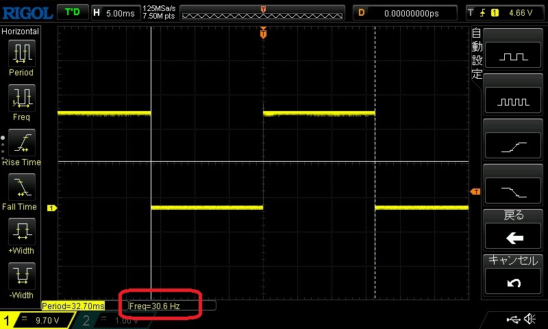
オシロスコープをLEDの部分に当てて実際の周波数を測ってみます。
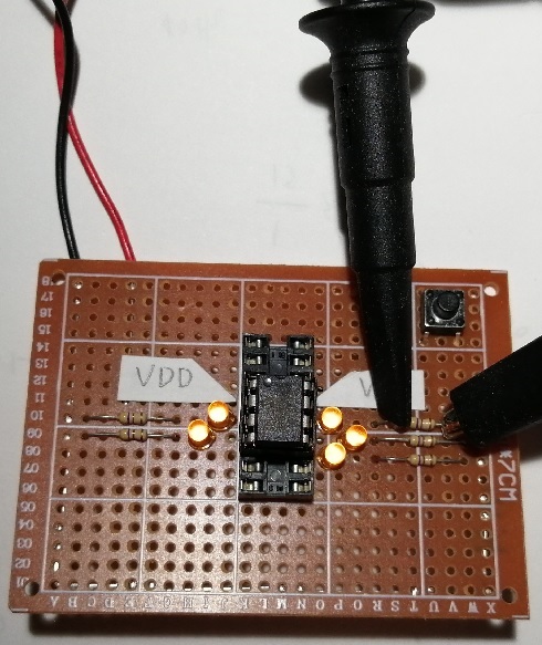
実際に測定すると30.6Hzと表示され、計算が大体正しいと言えるんではないかと思います。
▼古いデバイスであるPIC16F84でタイマー割り込み
PICマイコンが古いデバイスを拡張して新しいデバイスが開発されていると考えると、タイマー割り込みのような基本的な機能はプログラムの大きな変更なしに動作する気がします。
メモリーのアドレスなどは昔のデバイスでは違いますがC言語で隠蔽されて見えなくなっていますし、そのままいけるんじゃないか?と思い、
LEDを点滅させるの回路を使用し、プログラムを少し改造しました。
#include <stdio.h>
#include <stdlib.h>

#pragma config FOSC = HS        // Oscillator Selection bits (HS oscillator)
#pragma config WDTE = OFF       // Watchdog Timer (WDT disabled)
#pragma config PWRTE = ON       // Power-up Timer Enable bit (Power-up Timer is enabled)
#pragma config CP = OFF         // Code Protection bit (Code protection disabled)

#include <xc.h>
#define _XTAL_FREQ 10000000 //クロック周波数 __delay_ms()に必要

int main(int argc, char** argv) {
    TRISA = 0b00000000; //portAを1:入力、0:出力 全てを出力に設定
    TRISB = 0b00000000; //portBを1:入力、0:出力 全てを出力に設定

    OPTION_REG = 0b00000111; //プリスケーラ1:256
    TMR0IF = 0; // TMR0 レジスタのオーバーフローフラグをリセット
    TMR0IE = 1; // Timer0 割り込みを有効にする
    GIE = 1; // 割り込み許可
    while (1) {
    }
    return (EXIT_SUCCESS);
}

void __interrupt() isr(void) {
    static int i;
    if (TMR0IF) { // TMR0 レジスタがオーバーフローした
        TMR0IF = 0; // TMR0 レジスタのオーバーフローフラグをリセット
        if (i) {
            i = 0;
            PORTA = 0b00000000; //portAに出力
            PORTB = 0b00000000;
        } else {
            i = 1;
            PORTA = 0b11111111;
            PORTB = 0b11111111;
        }
    }
}
LEDの点滅プログラムに赤文字部分を追加しました。
このプログラムを動作させるとLEDが速い速度で点滅します。
どのくらいの速度で点滅しているのか計算してみると、
クロック周波数10MHz = 10000000Hz
(FOSC/4) にすると、10000000Hz / 4 = 2500000Hz
8bitプリスケーラ ( 1 / 256 ) × 8bitタイマー ( 1 / 256 ) = 1 / 65536
2500000Hz / 65536 = 38.146Hz
割り込み2回で1Hzを作っているため、38.146Hz / 2 = 19Hz
約19Hzで点滅している事になります。
オシロスコープで実際に測ってみると近い値になりました。
▼ PIC16F1827 でのタイマー割り込み
LEDを点滅させるの回路を使用しPIC16F84のプログラムとほとんど同じです。
#include <stdio.h>
#include <stdlib.h>
// CONFIG1
#pragma config FOSC = HS        // Oscillator Selection (HS Oscillator, High-speed crystal/resonator connected between OSC1 and OSC2 pins)
#pragma config WDTE = OFF       // Watchdog Timer Enable (WDT disabled)
#pragma config PWRTE = ON       // Power-up Timer Enable (PWRT enabled)
#pragma config MCLRE = ON       // MCLR Pin Function Select (MCLR/VPP pin function is MCLR)
#pragma config CP = OFF         // Flash Program Memory Code Protection (Program memory code protection is disabled)
#pragma config CPD = OFF        // Data Memory Code Protection (Data memory code protection is disabled)
#pragma config BOREN = ON       // Brown-out Reset Enable (Brown-out Reset enabled)
#pragma config CLKOUTEN = OFF   // Clock Out Enable (CLKOUT function is disabled. I/O or oscillator function on the CLKOUT pin)
#pragma config IESO = OFF       // Internal/External Switchover (Internal/External Switchover mode is disabled)
#pragma config FCMEN = OFF      // Fail-Safe Clock Monitor Enable (Fail-Safe Clock Monitor is disabled)
// CONFIG2
#pragma config WRT = OFF        // Flash Memory Self-Write Protection (Write protection off)
#pragma config PLLEN = OFF      // PLL Enable (4x PLL disabled)
#pragma config STVREN = ON      // Stack Overflow/Underflow Reset Enable (Stack Overflow or Underflow will cause a Reset)
#pragma config BORV = HI        // Brown-out Reset Voltage Selection (Brown-out Reset Voltage (Vbor), high trip point selected.)
#pragma config LVP = OFF        // Low-Voltage Programming Enable (High-voltage on MCLR/VPP must be used for programming)

#include <xc.h>
#define _XTAL_FREQ 10000000 //クロック周波数 __delay_ms()に必要

int main(int argc, char** argv) {
    TRISA = 0b00000000; //portAを1:入力、0:出力 全てを出力に設定
    TRISB = 0b00000000; //portBを1:入力、0:出力 全てを出力に設定

    OPTION_REG = 0b00000111; //プリスケーラ1:256
    TMR0IF = 0; // TMR0 レジスタのオーバーフローフラグをリセット
    TMR0IE = 1; // Timer0 割り込みを有効にする
    GIE = 1; // 割り込み許可
    while (1) {
    }
    return (EXIT_SUCCESS);
}

void __interrupt() isr(void) {
    static int i;
    if (TMR0IF) { // TMR0 レジスタがオーバーフローした
        TMR0IF = 0; // TMR0 レジスタのオーバーフローフラグをリセット
        if (i) {
            i = 0;
            PORTA = 0b00000000; //portAに出力
            PORTB = 0b00000000;
        } else {
            i = 1;
            PORTA = 0b11111111;
            PORTB = 0b11111111;
        }
    }
}
▲トップページ
>
マイコンなど